- British Pharmacopoeia Volume IV
- Appendices
Appendix XII B. Dissolution |


This test is provided to determine compliance with the dissolution requirements for solid dosage forms administered orally. In this chapter, a dosage unit is defined as 1 tablet or 1 capsule or the amount specified.
Apparatus 1 (Basket apparatus) The assembly consists of the following: a vessel, which may be covered, made of glass or other inert, transparent material1; a motor; a drive shaft; and a cylindrical basket (stirring element). The vessel is partially immersed in a suitable water-bath of any convenient size or heated by a suitable device such as a heating jacket. The water-bath or heating device permits maintaining the temperature inside the vessel at 37 ± 0.5 °C during the test and keeping the dissolution medium in constant, smooth motion. No part of the assembly, including the environment in which the assembly is placed, contributes significant motion, agitation, or vibration beyond that due to the smoothly rotating stirring element. Apparatus that permits observation of the preparation and stirring element during the test is preferable. The vessel is cylindrical, with a hemispherical bottom and a capacity of 1 litre. Its height is 160-210 mm and its inside diameter is 98-106 mm. Its sides are flanged at the top. A fitted cover may be used to retard evaporation2. The shaft is positioned so that its axis is not more than 2 mm at any point from the vertical axis of the vessel and rotates smoothly and without significant wobble that could affect the results. A speed-regulating device is used that allows the shaft rotation speed to be selected and maintained at a specified rate, within ± 4 per cent.
Shaft and basket components of the stirring element are fabricated of stainless steel, type 316 or equivalent, to the specifications shown in Figure 2.9.3.-1.
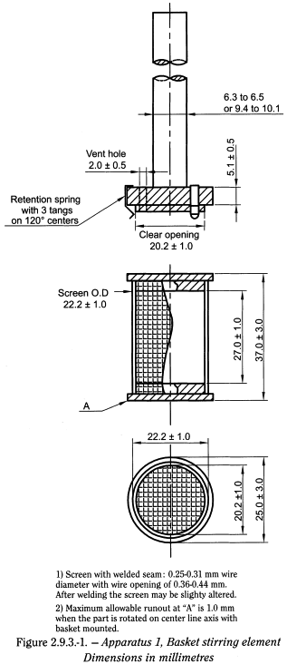
A basket having a gold coating of about 2.5 µm (0.0001 inch) thick may be used. The dosage unit is placed in a dry basket at the beginning of each test. The distance between the inside bottom of the vessel and the bottom of the basket is maintained at 25 ± 2 mm during the test.
Apparatus 2 (Paddle apparatus) Use the assembly from Apparatus 1, except that a paddle formed from a blade and a shaft is used as the stirring element. The shaft is positioned so that its axis is not more than 2 mm from the vertical axis of the vessel, at any point, and rotates smoothly without significant wobble that could affect the results. The vertical center line of the blade passes through the axis of the shaft so that the bottom of the blade is flush with the bottom of the shaft. The paddle conforms to the specifications shown in Figure 2.9.3.-2. The distance of 25 ± 2 mm between the bottom of the blade and the inside bottom of the vessel is maintained during the test. The metallic or suitably inert, rigid blade and shaft comprise a single entity. A suitable two-part detachable design may be used provided the assembly remains firmly engaged during the test. The paddle blade and shaft may be coated with a suitable coating so as to make them inert. The dosage unit is allowed to sink to the bottom of the vessel before rotation of the blade is started. A small, loose piece of non-reactive material, such as not more than a few turns of wire helix, may be attached to dosage units that would otherwise float. An alternative sinker device is shown in Figure 2.9.3.-3. Other validated sinker devices may be used.

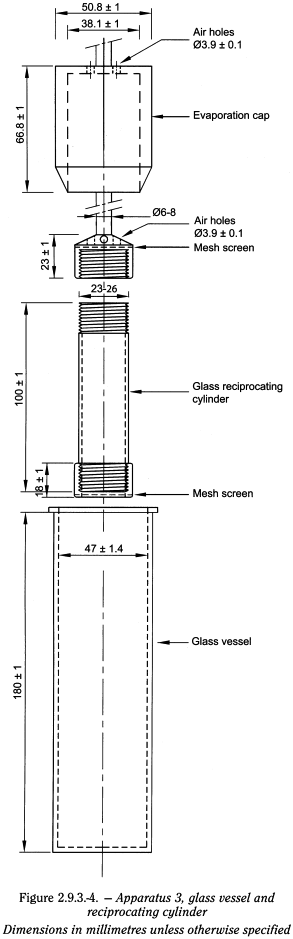
Apparatus 3 (Reciprocating cylinder) The assembly consists of a set of cylindrical, flat-bottomed glass vessels; a set of glass reciprocating cylinders; inert fittings (stainless steel type 316 or other suitable material) and screens that are made of suitable nonsorbing and nonreactive material, and that are designed to fit the tops and bottoms of the reciprocating cylinders; a motor and drive assembly to reciprocate the cylinders vertically inside the vessels, and if desired, index the reciprocating cylinders horizontally to a different row of vessels. The vessels are partially immersed in a suitable water-bath of any convenient size that permits holding the temperature at 37 ± 0.5 °C during the test. No part of the assembly, including the environment in which the assembly is placed, contributes significant motion, agitation, or vibration beyond that due to the smooth, vertically reciprocating cylinder. A device is used that allows the reciprocation rate to be selected and maintained at the specified dip rate, within ± 5 per cent. An apparatus that permits observation of the preparations and reciprocating cylinders is preferable. The vessels are provided with an evaporation cap that remains in place for the duration of the test. The components conform to the dimensions shown in Figure 2.9.3.-4 unless otherwise specified.

Apparatus 4 (Flow-through cell) The assembly consists of a reservoir and a pump for the dissolution medium; a flow-through cell; a water-bath that maintains the dissolution medium at 37 ± 0.5 °C. Use the specified cell size.
The pump forces the dissolution medium upwards through the flow-through cell. The pump has a delivery range between 240 ml/h and 960 ml/h, with standard flow rates of 4 ml/min, 8 ml/min, and 16 ml/min. It must deliver a constant flow (± 5 per cent of the nominal flow rate); the flow profile is sinusoidal with a pulsation of 120 ± 10 pulses/min. Non-pulsated flow may also be used.
The flow-through cell (see Figures 2.9.3.-5 and 2.9.3.-6) of transparent and inert material is mounted vertically, with a filter system that prevents escape of undissolved particles from the top of the cell; standard cell diameters are 12 mm and 22.6 mm; the bottom cone is usually filled with small glass beads of about 1 mm diameter, with 1 bead of about 5 mm positioned at the apex to protect the fluid entry tube; a tablet holder (see Figures 2.9.3.-5 and 2.9.3.-6) is available for positioning of special dosage forms. The cell is immersed in a water-bath, and the temperature is maintained at 37 ± 0.5 °C.
The apparatus uses a clamp mechanism and 2 O-rings for the fixation of the cell assembly. The pump is separated from the dissolution unit in order to shield the latter against any vibrations originating from the pump. The position of the pump must not be on a level higher than the reservoir flasks. Tube connections are as short as possible. Use suitably inert tubing, such as polytetrafluoroethylene, with a 1.6 mm inner diameter and inert flanged-end connections.
Apparatus suitability The determination of suitability of the apparatus to perform dissolution testing must include conformance to the dimensions and tolerances of the apparatus as given above. In addition, critical test parameters that have to be monitored periodically during use include volume and temperature of the dissolution medium, rotation speed (Apparatus 1 and 2, dip rate (Apparatus 3), and flow rate of medium (Apparatus 4).
Determine the acceptable performance of the dissolution test assembly periodically.
Procedure Place the stated volume of the dissolution medium (± 1 per cent) in the vessel of the specified apparatus. Assemble the apparatus, equilibrate the dissolution medium to 37 ± 0.5 °C, and remove the thermometer. The test may also be carried out with the thermometer in place, provided it is shown that results equivalent to those obtained without the thermometer are obtained.
Place 1 dosage unit in the apparatus, taking care to exclude air bubbles from the surface of the dosage unit. Operate the apparatus at the specified rate. Within the time interval specified, or at each of the times stated, withdraw a specimen from a zone midway between the surface of the dissolution medium and the top of the rotating basket or blade, not less than 1 cm from the vessel wall. Where multiple sampling times are specified, replace the aliquots withdrawn for analysis with equal volumes of fresh dissolution medium at 37 °C or, where it can be shown that replacement of the medium is not necessary, correct for the volume change in the calculation. Keep the vessel covered for the duration of the test and verify the temperature of the medium at suitable times. Perform the analysis using a suitable assay method3. Repeat the test with additional dosage units.
If automated equipment is used for sampling or the apparatus is otherwise modified, verification that the modified apparatus will produce results equivalent to those obtained with the apparatus described in this chapter, is necessary.
Dissolution medium A suitable dissolution medium is used. The volume specified refers to measurements made between 20 °C and 25 °C. If the dissolution medium is a buffered solution, adjust the solution so that its pH is within 0.05 units of the specified pH. Dissolved gases can cause bubbles to form, which may change the results of the test. In such cases, dissolved gases must be removed prior to testing4.
Time Where a single time specification is given, the test may be concluded in a shorter period if the requirement for minimum amount dissolved is met. Samples are to be withdrawn only at the stated times, within a tolerance of ± 2 per cent.
Procedure Proceed as described for conventional-release dosage forms.
Dissolution medium Proceed as described for conventional-release dosage forms.
Time The test-time points, generally 3, are expressed in hours.
Procedure Use Method A or Method B.
Method A
- — Acid stage Place 750 ml of 0.1 M hydrochloric acid in the vessel, and assemble the apparatus. Allow the medium to equilibrate to a temperature of 37 ± 0.5 °C. Place 1 dosage unit in the apparatus, cover the vessel and operate the apparatus at the specified rate. After 2 h of operation in 0.1 M hydrochloric acid, withdraw an aliquot of the fluid and proceed immediately as directed under Buffer stage. Perform an analysis of the aliquot using a suitable assay method.
- — Buffer stage Complete the operations of adding the buffer and adjusting the pH within 5 min. With the apparatus operating at the rate specified, add to the fluid in the vessel 250 ml of 0.20 M solution of trisodium phosphate dodecahydrate R that has been equilibrated to 37 ± 0.5 °C. Adjust, if necessary, with 2 M hydrochloric acid R or 2 M sodium hydroxide R to a pH of 6.8 ± 0.05. Continue to operate the apparatus for 45 min, or for the specified time. At the end of the time period, withdraw an aliquot of the fluid and perform the analysis using a suitable assay method.
Method B
- — Acid Stage Place 1000 ml of 0.1 M hydrochloric acid in the vessel and assemble the apparatus. Allow the medium to equilibrate to a temperature of 37 ± 0.5 °C. Place 1 dosage unit in the apparatus, cover the vessel, and operate the apparatus at the specified rate. After 2 h of operation in 0.1 M hydrochloric acid, withdraw an aliquot of the fluid, and proceed immediately as directed under Buffer stage. Perform an analysis of the aliquot using a suitable assay method.

- — Buffer stage For this stage of the procedure use buffer that has previously been equilibrated to a temperature of 37 ± 0.5 °C. Drain the acid from the vessel and add 1000 ml of pH 6.8 phosphate buffer, prepared by mixing 3 volumes of 0.1 M hydrochloric acid with 1 volume of 0.20 M solution of trisodium phosphate dodecahydrate R and adjusting, if necessary, with 2 M hydrochloric acid R or 2 M sodium hydroxide R to a pH of 6.8 ± 0.05. This may also be accomplished by removing from the apparatus the vessel containing the acid and replacing it with another vessel, containing the buffer and transferring the dosage unit to the vessel containing the buffer. Continue to operate the apparatus for 45 min, or for the specified time. At the end of the time period, withdraw an aliquot of the fluid and perform the analysis using a suitable assay method.
Time All test times stated are to be observed within a tolerance of ± 2 per cent, unless otherwise specified.
Procedure Place the stated volume of the dissolution medium (± 1 per cent) in each vessel of the apparatus. Assemble the apparatus, equilibrate the dissolution medium to 37 ± 0.5 °C, and remove the thermometer. Place 1 dosage unit in each of the reciprocating cylinders, taking care to exclude air bubbles from the surface of each dosage unit, and immediately operate the apparatus as specified. During the upward and downward stroke, the reciprocating cylinder moves through a total distance of 9.9-10.1 cm. Within the time interval specified, or at each of the times stated, raise the reciprocating cylinders and withdraw a portion of the medium from a zone midway between the surface of the dissolution medium and the bottom of each vessel. Perform the analysis as directed. If necessary, repeat the test with additional dosage units.

Replace the aliquot withdrawn for analysis with equal volumes of fresh dissolution medium at 37 °C or, where it can be shown that replacement of the medium is not necessary, correct for the volume change in the calculation. Keep the vessel covered with the evaporation cap for the duration of the test and verify the temperature of the medium at suitable times.
Dissolution medium Proceed as described for conventional-release dosage forms under Apparatus 1 and 2.
Time Proceed as described for conventional-release dosage forms under Apparatus 1 and 2.
Procedure Proceed as described for conventional-release dosage forms under Apparatus 3.
Dissolution medium Proceed as described for prolonged-release dosage forms under Apparatus 1 and 2.
Time Proceed as described for prolonged-release dosage forms under Apparatus 1 and 2.
Procedure Proceed as described for delayed-release dosage forms, Method B, under Apparatus 1 and 2, using one row of vessels for the acid stage media and the following row of vessels for the buffer stage media, and using the volume of medium specified (usually 300 ml).
Time Proceed as directed for delayed-release dosage forms under Apparatus 1 and 2.
Procedure Place the glass beads into the cell specified. Place 1 dosage unit on top of the beads or, if specified, on a wire carrier. Assemble the filter head and fix the parts together by means of a suitable clamping device. Introduce by the pump the dissolution medium warmed to 37 ± 0.5 °C through the bottom of the cell to obtain the flow rate specified and measured with an accuracy of 5 per cent. Collect the eluate by fractions at each of the times stated. Perform the analysis as directed. Repeat the test with additional dosage units.
Dissolution medium Proceed as described for conventional-release dosage forms under Apparatus 1 and 2
Time Proceed as described for conventional-release dosage forms under Apparatus 1 and 2.
Procedure Proceed as described for conventional-release dosage forms under Apparatus 4.
Dissolution medium Proceed as described for conventional-release dosage forms under Apparatus 4.
Time Proceed as described for conventional-release dosage forms under Apparatus 4.
Procedure Proceed as described for delayed-release dosage forms under Apparatus 1 and 2, using the specified media.
Time Proceed as described for delayed-release dosage forms under Apparatus 1 and 2.
Unless otherwise specified, the requirements are met if the quantities of active substance dissolved from the dosage units tested conform to Table 2.9.3.-1. Continue testing through the 3 levels unless the results conform at either S1 or S2. The quantity Q, is the specified amount of dissolved active substance, expressed as a percentage of the labelled content; the 5 per cent, 15 per cent, and 25 per cent values in the Table are percentages of the labelled content so that these values and Q are in the same terms.

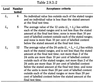
Unless otherwise specified, the requirements are met if the quantities of active substance dissolved from the dosage units tested conform to Table 2.9.3.-2. Continue testing through the 3 levels unless the results conform at either L1 or L2. Limits on the amounts of active substance dissolved are expressed in terms of the percentage of labelled content. The limits embrace each value of Qi, the amount dissolved at each specified fractional dosing interval. Where more than one range is specified, the acceptance criteria apply individually to each range.
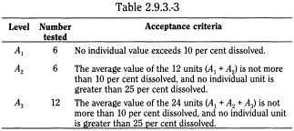
Acid stage Unless otherwise specified, the requirements of this portion of the test are met if the quantities, based on the percentage of the labelled content of active substance dissolved from the units tested conform to Table 2.9.3.-3. Continue testing through the 3 levels unless the results of both acid and buffer stages conform at an earlier level.
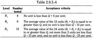
Buffer stage Unless otherwise specified, the requirements are met if the quantities of active substance dissolved from the units tested conform to Table 2.9.3.-4. Continue testing through the 3 levels unless the results of both stages conform at an earlier level. The value of Q in Table 2.9.3.-4 is 75 per cent dissolved unless otherwise specified. The quantity, Q, is the specified total amount of active substance dissolved in both the acid and buffer stages, expressed as a percentage of the labelled content. The 5 per cent, 15 per cent and 25 per cent values in the Table are percentages of the labelled content so that these values and Q are in the same terms.
The following section is published for information
In the determination of the dissolution rate of the active substance(s) of a solid dosage form, the following are to be specified:
- — the apparatus to be used, and in cases where the flow-through apparatus is specified, which flow-through cell is to be used;
- — the composition, the volume and the temperature of the dissolution medium;
- — the rotation speed or the flow rate of the dissolution medium;
- — the time, the method and the amount for sampling of the test solution or the conditions for continuous monitoring;
- — the method of analysis;
- — the acceptance criteria.
The choice of apparatus to be used depends on the physico-chemical characteristics of the dosage form. When a large quantity of dissolution medium is required to ensure sink conditions, or when a change of pH is necessary, the flow-through apparatus may be preferred.
The use of the basket and the paddle apparatus and the reciprocating cylinder apparatus is generally based on the principle of operating under "sink conditions", i.e. in such a manner that the material already in solution does not exert a significant modifying effect on the rate of dissolution of the remainder. "Sink conditions" normally occur in a volume of dissolution medium that is at least 3 to 10 times the saturation volume.
In general, an aqueous medium is used. The composition of the medium is chosen on the basis of the physico-chemical characteristics of the active substance(s) and excipient(s) within the range of conditions to which the dosage form is likely to be exposed after its administration. This applies in particular to the pH and the ionic strength of the dissolution medium.
The pH of the dissolution medium is usually set between pH 1 and 8. In justified cases, a higher pH may be needed. For the lower pH values in the acidic range, 0.1 M hydrochloric acid is normally used. Recommended dissolution media are described hereafter.
Water is recommended as a dissolution medium only when it is proven that the pH variations do not have an influence on the dissolution characteristics.
In specific cases, dissolution media may contain enzymes, surfactants, further inorganic substances and organic substances. For the testing of preparations containing poorly aqueous-soluble active substances, modification of the medium may be necessary. In such circumstances, a low concentration of surfactant is recommended; it is recommended to avoid the use of organic solvents.
Gases dissolved in the dissolution medium can affect the results of the dissolution test. This is true, in particular, for the flow-through apparatus where de-aeration of the medium is necessary to avoid the formation of gas bubbles in the flow-through cell. A suitable method of de-aeration is as follows: heat the medium while stirring gently to about 41 °C, immediately filter under vacuum using a filter with a porosity of 0.45 µm or less, with vigorous stirring, and continue stirring under vacuum for about 5 min. Other de-aeration techniques for removal of dissolved gases may be used.
Using the paddle or basket apparatus, the volume of dissolution medium is normally 500-1000 ml. A stirring speed of between 50 r/min and 100 r/min is normally chosen; it must not exceed 150 r/min.
For the flow-through apparatus, the liquid flow rate is normally set between 4 ml/min and 50 ml/min.
The following dissolution media may be used.

The composition and preparation of these various media are indicated below.
- — 0.2 M hydrochloric acid,
- — 0.2 M sodium chloride Dissolve 11.69 g of sodium chloride R in water R and dilute to 1000.0 ml with the same solvent.
For preparing media with the following pH, place 250.0 ml of 0.2 M sodium chloride in a 1000 ml volumetric flask, add the specified volume of 0.2 M hydrochloric acid, then dilute to 1000.0 ml with water R (see Table 2.9.3.-6.).

The hydrochloric acid media may also be prepared by replacing sodium chloride by potassium chloride.
- — 2 M acetic acid Dilute 120.0 g of glacial acetic acid R to 1000.0 ml with water R.
- — Acetate buffer solution pH 4.5 Dissolve 2.99 g of sodium acetate R in water R. Add 14.0 ml of 2 M acetic acid and dilute to 1000.0 ml with water R.
- — Acetate buffer solution pH 5.5 Dissolve 5.98 g of sodium acetate R in water R. Add 3.0 ml of 2 M acetic acid and dilute to 1000.0 ml with water R.
- — Acetate buffer solution pH 5.8 Dissolve 6.23 g of sodium acetate R in water R. Add 2.1 ml of 2 M acetic acid and dilute to 1000.0 ml with water R.
For preparing buffers with the pH values indicated in Table 2.9.3.-7, place 250.0 ml of 0.2 M potassium dihydrogen phosphate R in a 1000 ml volumetric flask, add the specified volume of 0.2 M sodium hydroxide, then dilute to 1000.0 ml with water R.
- — Phosphate buffer solution pH 4.5 Dissolve 13.61 g of potassium dihydrogen phosphate R in 750 ml of water R. Adjust the pH (2.2.3) if necessary with 0.1 M sodium hydroxide or with 0.1 M hydrochloric acid. Dilute to 1000.0 ml with water R.
- — Phosphate buffer solution pH 5.5 R.
- — Phosphate buffer solution pH 6.8 R1.
- — Buffer solution pH 7.2 R.
- — 0.33 M phosphate buffer solution pH 7.5 R.

Mix 250.0 ml of a solution containing 6.8 g of potassium dihydrogen phosphate R, 77.0 ml of 0.2 M sodium hydroxide and 500 ml of water R. Add 10.0 g of pancreas powder R, mix and adjust the pH (2.2.3), if necessary. Dilute to 1000.0 ml with water R.
Dissolve 2.0 g of sodium chloride R and 3.2 g of pepsin powder R in water R. Add 80 ml of 1 M hydrochloric acid and dilute to 1000.0 ml with water R. If required, pepsin powder may be omitted.
For a test involving increasing pH, one of the following sequences may be used:
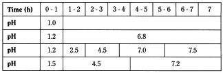
To achieve this pH variation, it is possible either:
- — to substitute one buffer solution for another (whole substitution);
- — to remove only half of the medium each time (half change method) and replace it with a buffer solution of higher pH: the initial pH is 1.2 and the second solution is phosphate buffer solution pH 7.5;
- — to an initial solution at pH 1.5, add a dose of a powder mixture containing tris(hydroxymethyl)aminomethane R and anhydrous sodium acetate R to obtain pH 4.5 and a second dose to obtain pH 7.2, as described below:
- — hydrochloric acid pH 1.5 Dissolve 2 g of sodium chloride R in water R, add 31.6 ml of hydrochloric acid R and dilute to 1000.0 ml with water R;
- — buffer solution pH 4.5 Mix 2.28 g of tris(hydroxymethyl)aminomethane R with 1.77 g of anhydrous sodium acetate R. Dissolve this mixture in the hydrochloric acid solution pH 1.5 described above;
- — buffer solution pH 7.2 Mix 2.28 g of tris(hydroxymethyl)aminomethane R with 1.77 g of anhydrous sodium acetate R. Dissolve this mixture in the buffer solution pH 4.5 described above.
The flow-through cell may be used for the continuous change of pH.
Due to the nature of the test method, quality by design is an important qualification aspect for in vitro dissolution test equipment. Any irregularities such as vibration or undesired agitation by mechanical imperfections are to be avoided.
Qualification of the dissolution test equipment has to consider the dimensions and tolerances of the apparatus. Critical test parameters, such as temperature and volume of dissolution medium, rotation speed or liquid flow rate, sampling probes and procedures have to be monitored periodically during the periods of use.
The performance of the dissolution test equipment may be monitored by testing a reference product which is sensitive to hydrodynamic conditions. Such tests may be performed periodically or continuously for comparative reasons with other laboratories.
During testing, critical inspection and observation are required. This approach is especially important to explain any out-lying results.
Validation of automated systems, whether concerning the sampling and analytical part or the dissolution media preparation and test performance, has to consider accuracy, precision, and the avoidance of contamination by any dilutions, transfers, cleaning and sample or solvent preparation procedures.
The dissolution specification is expressed as the quantity Q of the active substance as a percentage of the content stated on the product label, which is dissolved in a specified time frame.
Unless otherwise specified, the value of Q is 75 per cent. In most cases, when tested under reasonable and justified test conditions at least 75 per cent of the active substance is released within 45 min. Typically, one limit is specified to ensure that most of the active substance is dissolved within the pre-set time period.
In cases where a longer release time than that recommended above is justified, limits at 2 time intervals may be specified.
A manufacturer's dissolution specification for prolonged-release dosage forms is normally expected to consist of 3 or more points. The first specification point is intended to prevent unintended rapid release of the active substance ('dose dumping'). It is therefore set after a testing period corresponding to a dissolved amount of typically 20 per cent to 30 per cent. The second specification point defines the dissolution pattern and so is set at around 50 per cent release. The final specification point is intended to ensure almost complete release which is generally understood as more than 80 per cent release.
A delayed-release dosage form may release the active substance(s) fractionally or totally according to the formulation design when tested in different dissolution media, e.g. in increasing pH conditions. Dissolution specifications have, therefore, to be decided from case to case.
Gastro-resistant dosage forms require at least 2 specification points in a sequential test and 2 different specifications in a parallel test. In a sequential test, the first specification point is set after 1 h or 2 h in acidic medium and the second one at a pre-set time period of testing in an adequate buffer solution (preferably pH 6.8). Unless otherwise specified, the value of Q is 75 per cent.
The following additional points apply to monographs of the British Pharmacopoeia.
The choice of the apparatus to be used depends on the physico-chemical characteristics of the dosage form. When this Appendix is invoked in an individual tablet or capsule monograph of the British Pharmacopoeia, use Apparatus I unless otherwise directed.
The dissolution medium is that specified in the individual monograph. Unless otherwise indicated in the monograph, withdraw samples at 45 minutes.
Where one tablet or capsule is directed to be placed in the apparatus, for each of the six tablets or capsules tested the amount of active ingredient in solution is not less than 70% of the prescribed or stated amount, unless otherwise specified in the monograph, except that if one fails this requirement a further six may be tested individually and all must comply. Where two or more tablets or capsules are directed to be placed together in the apparatus, a total of six replicate tests are carried out. In each test the amount of active ingredient in solution per tablet or capsule is not less than 70% of the prescribed or stated amount, unless otherwise specified in the monograph. No retesting is permitted.
Where capsule shells interfere with the analysis, remove the contents of no fewer than six capsules as completely as possible and dissolve the empty capsule shells in the specified volume of dissolution medium. Carry out the test as directed in the individual monograph and make any necessary correction. Correction factors should not be greater than 25% of the labelled content.
(Ph. Eur. method 2.9.4)This test is used to determine the dissolution rate of the active ingredients of transdermal patches.
Equipment Use the paddle and vessel assembly from the paddle apparatus described in the dissolution test for solid oral dosage forms (2.9.3) with the addition of a stainless steel disk assembly (SSDA) in the form of a net with an aperture of 125 µm (see Figure 2.9.4.-1).

The SSDA holds the system at the bottom of the vessel and is designed to minimise any dead volume between the SSDA and the bottom of the vessel. The SSDA holds the patch flat, with the release surface uppermost and parallel to the bottom of the paddle blade. A distance of 25 ± 2 mm between the bottom of the paddle blade and the surface of the SSDA is maintained during the test (see Figure 2.9.4.-2). The temperature is maintained at 32 ± 0.5 °C. The vessel may be covered during the test to minimise evaporation.
Procedure Place the prescribed volume of the dissolution medium in the vessel and equilibrate the medium to the prescribed temperature. Apply the patch to the SSDA, ensuring that the release surface of the patch is as flat as possible. The patch may be attached to the SSDA by a prescribed adhesive or by a strip of a double-sided adhesive tape. The adhesive or tape are previously tested for the absence of interference with the assay and of adsorption of the active ingredient(s). Press the patch, release surface facing up, onto the side of the SSDA made adhesive. The applied patch must not overlap the borders of the SSDA. For this purpose and provided that the preparation is homogeneous and uniformly spread on the outer covering, an appropriate and exactly measured piece of the patch may be cut and used for testing the dissolution rate. This procedure may also be necessary to achieve appropriate sink conditions. This procedure must not be applied to membrane-type patches. Place the patch mounted on the SSDA flat at the bottom of the vessel with the release surface facing upwards. Immediately rotate the paddle at 100 r/min, for example. At predetermined intervals, withdraw a sample from the zone midway between the surface of the dissolution medium and the top of the blade, not less than 1 cm from the vessel wall.
Perform the assay on each sample, correcting for any volume losses, as necessary. Repeat the test with additional patches.

Equipment Use the paddle and vessel assembly from the paddle apparatus described in the dissolution test for solid oral dosage forms (2.9.3) with the addition of the extraction cell (cell).
The cell is made of chemically inert materials and consists of a support, a cover and, if necessary, a membrane placed on the patch to isolate it from the medium that may modify or adversely affect the physico-chemical properties of the patch (see Figure 2.9.4.-3).

Support The central part of the support forms a cavity intended to hold the patch. The cavity has a depth of 2.6 mm and a diameter that is appropriate to the size of the patch to be examined. The following diameters can be used: 27 mm, 38 mm, 45 mm, 52 mm, corresponding to volumes of 1.48 ml, 2.94 ml, 4.13 ml, 5.52 ml, respectively.
Cover The cover has a central opening with a diameter selected according to the size of the patch to be examined. The patch can thus be precisely centred, and its releasing surface limited. The following diameters may be used: 20 mm, 32 mm, 40 mm, 50 mm corresponding to areas of 3.14 cm2, 8.03 cm2, 12.56 cm2, 19.63 cm2, respectively. The cover is held in place by nuts screwed onto bolts projecting from the support. The cover is sealed to the support by a rubber ring set on the reservoir.
Extraction cell The cell holds the patch flat, with the release surface uppermost and parallel to the bottom of the paddle blade. A distance of 25 ± 2 mm is maintained between the paddle blade and the surface of the patch (see Figure 2.9.4.-4). The temperature is maintained at 32 ± 0.5 °C. The vessel may be covered during the test to minimise evaporation.
Procedure Place the prescribed volume of the dissolution medium in the vessel and equilibrate the medium to the prescribed temperature. Precisely centre the patch in the cell with the releasing surface uppermost. Close the cell, if necessary applying a hydrophobic substance (for example, petrolatum) to the flat surfaces to ensure the seal, and ensure that the patch stays in place. Introduce the cell flat into the bottom of the vessel with the cover facing upwards. Immediately rotate the paddle, at 100 r/min for example. At predetermined intervals, withdraw a sample from the zone midway between the surface of the dissolution medium and the top of the paddle blade, not less than 1 cm from the vessel wall.
Perform the assay on each sample, correcting for any volume losses, as necessary. Repeat the test with additional patches.

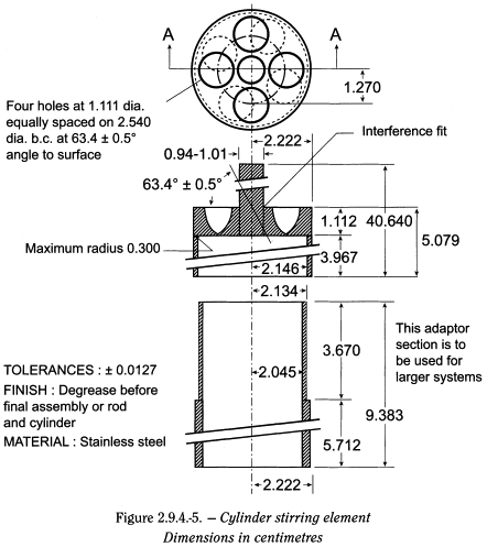
Equipment Use the assembly of the paddle apparatus described in the dissolution test for solid oral dosage forms (2.9.3). Replace the paddle and shaft with a stainless steel cylinder stirring element (cylinder) (see Figure 2.9.4.-5). The patch is placed on the cylinder at the beginning of each test. The distance between the inside bottom of the vessel and the cylinder is maintained at 25 ± 2 mm during the test. The temperature is maintained at 32 ± 0.5 °C. The vessel is covered during the test to minimise evaporation.
Procedure Place the prescribed volume of the dissolution medium in the vessel and equilibrate the medium to the prescribed temperature. Remove the protective liner from the patch and place the adhesive side on a piece of suitable inert porous membrane that is at least 1 cm larger on all sides than the patch. Place the patch on a clean surface with the membrane in contact with this surface. Two systems for adhesion to the cylinder may be used:
- — apply a suitable adhesive to the exposed membrane borders and, if necessary, to the back of the patch,
- — apply a double-sided adhesive tape to the external wall of the cylinder.
Using gentle pressure, carefully apply the non-adhesive side of the patch to the cylinder, so that the release surface is in contact with the dissolution medium and the long axis of the patch fits around the circumference of the cylinder.
The system for adhesion used is previously tested for absence of interference with the assay and of adsorption of the active ingredient(s).
Place the cylinder in the apparatus, and immediately rotate the cylinder at 100 r/min, for example. At determined intervals, withdraw a sample of dissolution medium from a zone midway between the surface of the dissolution medium and the top of the rotating cylinder, and not less than 1 cm from the vessel wall.
Perform the assay on each sample as directed in the individual monograph, correcting for any volume withdrawn, as necessary. Repeat the test with additional patches.
Interpretation The requirements are met if the quantity of active ingredient(s) released from the patch, expressed as the amount per surface area per time unit, is within the prescribed limits at the defined sampling times.
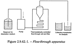
The apparatus (see Figure 2.9.42.-1) consists of:
- — A reservoir for the dissolution medium.
- — A pump that forces the dissolution medium upwards through the flow-through cell.
- — A flow-through cell shown in Figure 2.9.42.-2 specifically intended for lipophilic solid dosage forms such as suppositories and soft capsules. It consists of 3 transparent parts which fit into each other. The lower part (1) is made up of 2 adjacent chambers connected to an overflow device.
- The dissolution medium passes through chamber A and is subjected to an upwards flow. The flow in chamber B is downwards directed to a small-size bore exit which leads upwards to a filter assembly. The middle part (2) of the cell has a cavity designed to collect lipophilic excipients which float on the dissolution medium. A metal grill serves as a rough filter. The upper part (3) holds a filter unit for paper, glass fibre or cellulose filters.
- — A water-bath that will maintain the dissolution medium at 37 ± 0.5 °C.
Dissolution medium If the dissolution medium is buffered, adjust its pH to within ± 0.05 units of the prescribed value. Remove any dissolved gases from the dissolution medium before the test since they can cause the formation of bubbles that significantly affect the results.
Place 1 unit of the preparation to be examined in chamber A. Close the cell with the prepared filter assembly. At the beginning of the test, chamber A requires air removal via a small orifice connected to the filter assembly. Heat the dissolution medium to an appropriate temperature taking the melting point of the preparation into consideration. Using a suitable pump, introduce the warmed dissolution medium through the bottom of the cell to obtain a suitable continuous flow through an open or closed circuit at the prescribed rate (± 5 per cent). When the dissolution medium reaches the overflow, air starts to escape through the capillary and chamber B fills with the dissolution medium. The preparation spreads through the dissolution medium according to its physico-chemical properties.
In justified and authorised cases, representative fractions of large volume suppositories may be tested.

Samples are always collected at the outlet of the cell, irrespective of whether the circuit is opened or closed.
Filter the liquid removed using an inert filter of appropriate pore size that does not cause significant adsorption of the active substance from the solution and does not contain substances extractable by the dissolution medium that would interfere with the prescribed analytical method. Proceed with analysis of the filtrate as prescribed.
The quantity of the active substance dissolved in a specified time is expressed as a percentage of the content stated on the label.
The test is used to determine the dissolution rate of active substances in medicated chewing gums. This is done by applying a mechanical kneading procedure to a piece of gum placed in a small chamber designed to simulate the process of chewing.
The chewing apparatus (Figure 2.9.25.-1) consists of:
- — 1 chewing chamber,
- — 1 vertical piston,
- — 2 horizontal pistons with O-rings and sealing rings.
The chewing chamber consists of 4 individual parts:
- — 1 central chamber,
- — 1 funnel (Figure 2.9.25.-2),
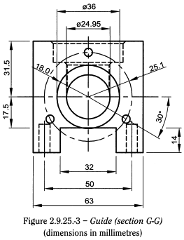
- — 2 guides with bushes (Figure 2.9.25.-3).
Funnel and guides are mounted on the central chamber. The O-rings are incorporated in the piston recess with the sealing ring round it; the sealing rings ensure that the chamber is watertight. The horizontal pistons are placed in the chewing chamber through the guides.


The gum is artificially chewed by the horizontal pistons, and the vertical piston ensures that the gum stays in the right place between chews.
Machine speed is controlled to ensure a constant cycle. One cycle (chew) is defined as follows: the horizontal pistons start from their outermost position, move to their innermost position and back to their outermost position. Within one cycle, the vertical piston moves from its lowest position to its uppermost position and back to its lowest position.
Each horizontal piston has a stroke of 25.0 mm. The maximum distance between these 2 pistons is 50 mm. The minimum distance between the 2 horizontal pistons is 0.1 mm to 1.0 mm. The vertical piston has a stroke of 22.0 mm.
Horizontal piston movement is controlled, so that the 2 pistons are at their innermost position at the same time. Vertical piston movement is controlled, so it does not conflict with the movement of the horizontal pistons.
If necessary, the machine can be constructed so that the horizontal pistons rotate around their own axes in opposite direction to each other by the end of the chew in order to obtain maximum chewing.
All parts of the apparatus that may come in contact with the preparation or the dissolution medium are chemically inert and do not adsorb, react or interfere with the sample.
For each determination, the following information is needed:
- — composition, volume and temperature of the dissolution medium,
- — number of chews per minute,
- — time and sampling method,
- — whether the analysis is performed on the gum residue or on the dissolution medium,
- — method of analysis.
Place the prescribed volume of dissolution medium in the chewing chamber, usually 20 ml of phosphate buffer solution pH 6.0 R2. Maintain the medium temperature at 37 ± 0.5 °C using an electrical device with external control. Set the piston speed at the prescribed number of chews per minute (usually 60). Accurately weigh a portion of gum or the whole gum, put it into the chewing chamber and start the machine.
Stop the apparatus at the prescribed time. Remove the gum residue and take a sample of the dissolution medium. Determine the content of active substance(s) by a suitable method. Medium replacement may be made after each sampling procedure; compensation by calculation of medium volume change or sample dilution is needed. Alternatively, determine the content of active substance(s) remaining in the gum residue. Carry out the test successively on 6 medicated chewing gums.
The quantity of active substance(s) dissolved in a specified time is expressed as a percentage of the content stated on the label.
The test is intended to determine the intrinsic dissolution rate of pure solid substances following compaction. It is carried out under specified experimental conditions such that a practical measure of the intrinsic dissolution rate is obtained.
The intrinsic dissolution rate is a theoretical value referring to pure solid substances having null porosity, but, practically, intrinsic dissolution rate is determined on substances having a minimal porosity.
The intrinsic dissolution rate is defined as the dissolution rate of pure substances following compaction under the condition of constant surface area. Its assessment is useful in the characterisation of active substances and excipients.
The dissolution rate of pure substances can be affected by all the solid state properties such as crystal habit, crystallinity, amorphism, polymorphism, pseudo-polymorphism, particle size and specific surface area. In addition, it can also be influenced by extrinsic factors (test conditions), such as hydrodynamics, temperature, viscosity, pH, buffer strength and ionic strength of the dissolution medium.
The assessment of intrinsic dissolution rate of a solid substance involves the preparation of a compact. Assurance of appropriate compaction properties of the powder to be tested is needed prior to performing the test.
The intrinsic dissolution rate is determined by exposing a constant area of the compacted substance to an appropriate dissolution medium, while maintaining constant stirring rate, temperature, ionic strength and pH.
The intrinsic dissolution rate is expressed in terms of dissolved mass of substance per time per exposed area, typically in milligrams per minute per square centimetre (mg·min-1·cm-2).
A typical apparatus consists of a punch and die fabricated out of hardened steel. The base of the die has 3 threaded holes for the attachment of a surface plate made of polished steel, providing a mirror-smooth base for the compact. The die has a 0.1-1.0 cm diameter cavity into which a measured amount of the powder to be tested is placed. The punch is then inserted in the die cavity and the material is compressed, generally using a benchtop hydraulic press. A hole through the head of the punch allows insertion of a metal rod to facilitate removal from the die after the test. A compact is formed in the cavity with a single face of defined area exposed on the bottom of the die (Figure 2.9.29.-1). The bottom of the die cavity is threaded so that at least 50-75 per cent of the compact can dissolve without falling out of the die. The top of the die has a threaded shoulder that allows it to be attached to a holder. The holder is mounted on a laboratory stirring device, and the entire die, with the compact still in place, is immersed in the dissolution medium and rotated by the stirring device.

Weigh the material onto a piece of weighing paper. Attach the surface plate to the underside of the die, and secure it with the 3 provided screws. Transfer the sample of powder tested into the die cavity. Place the punch into the chamber, and secure the metal plate on the top of the assembly. Compress the powder using a hydraulic press by applying a suitable pressure for a sufficient dwell time to ensure a stable compact with minimal porosity; the disintegration of the compact has to be prevented as far as possible, since it would cause an increase in surface area and hence in dissolution rate. Detach the surface plate, and screw the die with punch still in place into the holder. Tighten securely. Remove all loose powder from the surface of the die by blowing compressed air or nitrogen across the surface of the compact.
Slide the die-holder assembly into the dissolution test chuck and tighten. Position the shaft in the spindle so that when the test head is lowered, the exposed surface of the compact will be 3.8 cm from the bottom of the vessel. The disc assembly is aligned to minimise wobble and air bubbles are not allowed to form as this could decrease the compact surface in contact with the dissolution medium. If possible, sink conditions are maintained throughout the test. However, in order to obtain detectable concentrations of solute, the use of a relatively small volume of medium may be necessary as a consequence of the limited surface available for dissolution.
Warm the dissolution medium to the temperature chosen for the test. Lower the test head into position before rotation. Care should be taken to ensure that air bubbles are excluded from the surface of the compact as this could decrease the compact surface in contact with the dissolution medium. Operate the apparatus immediately at the speed of rotation chosen for the test.
Collect samples at fixed time intervals and assay them by means of an analytical method of suitable sensitivity and accuracy.
The data for the cumulative amount dissolved at each time point are corrected for sampling losses. To calculate the intrinsic dissolution rate, plot the cumulative amount of sample dissolved per unit area of the compact against time. The cumulative amount dissolved per unit area is given by the cumulative amount dissolved at each time point divided by the surface area exposed. Linear regression is then performed on the normalised experimental data relevant to an appropriate time interval preceding the possible disintegration of the compact. The intrinsic dissolution rate of the substance tested, expressed in milligrams per minute per square centimetre, is determined from the slope of the regression line. The result for intrinsic dissolution rate must be accompanied by a statement of the precise conditions of compact preparation and test method (dissolution medium, volume of medium used, stirring rate, temperature etc.).
NOTE: When necessary and justified, an apparatus with a different configuration may be used, such as a die holder that holds the compact in a fixed vertical position, with agitation provided by a paddle positioned at a defined distance from the surface of the compact.
This method is mainly used to determine the apparent dissolution rate of pure solid substances. It may also be used for the determination of the apparent dissolution rate of active substances in preparations presented as powders or granules.
All parts of the apparatus that may come into contact with the sample or the dissolution medium are chemically inert and do not adsorb, react with, or interfere with the test sample. No part of the assembly or its environment contributes significant motion, agitation or vibration beyond that resulting from the flow-through system.
Apparatus that permits observation of the sample is preferable.
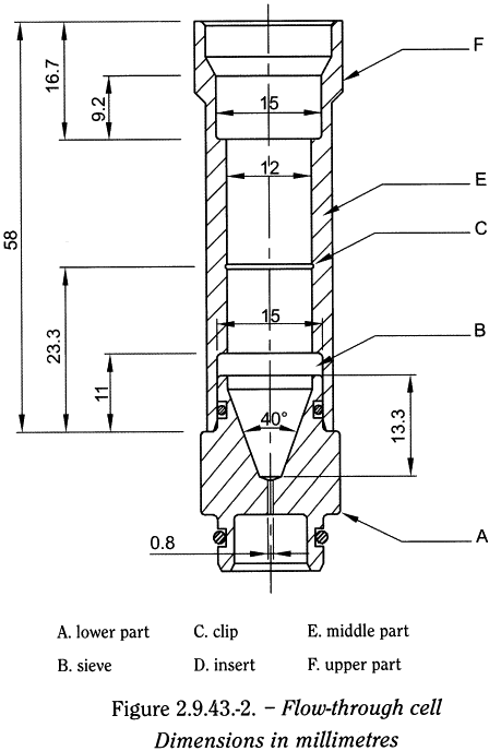
The apparatus (see Figure 2.9.43.-1) consists of:
- — a reservoir for the dissolution medium;
- — a pump that forces the dissolution medium upwards through the flow-through cell;
- — a flow-through cell, preferably of transparent material, mounted vertically with a filter system preventing escape of undissolved particles;
- — a water-bath that will maintain the dissolution medium at the chosen temperature (generally 37 ± 0.5 °C).

The flow-through cell shown in Figure 2.9.43.-2 consists of 3 parts that fit into each other. The lower part supports a system of grids and filters on which the powder is placed. The middle part, which fits onto the lower part, contains an insert that sieves the sample when the dissolution medium flows through the cell. This insert is made up of 2 parts: a conical sieve that is placed on the sample and a clip placed midway down the middle part to hold the sieve in place when the dissolution medium passes through. A 2nd filtration assembly (grid and filter) is placed on top of the middle part before fitting the upper part through which the dissolution medium flows out of the cell.
If the dissolution medium is buffered, adjust its pH to within ± 0.05 units. Remove any dissolved gases from the dissolution medium before the test, since they can cause the formation of bubbles, which significantly affect the results.
Place a bead of 5 ± 0.5 mm diameter at the bottom of the cone of the lower part followed by glass beads of suitable size, preferably of 1 ± 0.1 mm diameter. Place a sieve (with 0.2 mm apertures), a suitable filter and a 2nd sieve on top of the lower part. Fit the middle part onto the lower part. Weigh the assembly. Place the sample on the filtration assembly and weigh the sample in the cell. Place the sieve of the insert, cone upwards, on the sample, and position the clip midway down the middle part. Place a sieve (with 0.2 mm apertures) and a suitable filter on top of the middle part. Fit the upper part. Heat the dissolution medium to the chosen temperature. Using a suitable pump, introduce the dissolution medium through the bottom of the cell to obtain a suitable continuous flow through an open or closed circuit at the prescribed rate ± 5 per cent.
Samples of dissolution medium are collected at the outlet of the cell, irrespective of whether the circuit is opened or closed.
Immediately filter the liquid removed using an inert filter of appropriate pore size that does not cause significant adsorption of the substances from the solution and does not contain substances extractable by the dissolution medium that would interfere with the prescribed analytical method. Proceed with the analysis of the filtrate as prescribed.
When the test is performed for batch release purposes, an adequate number of replicates is carried out.
The results are expressed as:
- — the amount of dissolved substance by time unit (if the dissolution is linear);
- — the dissolution time of the whole sample and at appropriate intermediate stages.
1 The materials must not sorb, react, or interfere with the preparation to be tested. The materials must not sorb, react, or interfere with the preparation to be tested.
2 If a cover is used, it provides sufficient openings to allow ready insertion of the thermometer and withdrawal of samples. If a cover is used, it provides sufficient openings to allow ready insertion of the thermometer and withdrawal of samples.
3 Test specimens are filtered immediately upon sampling unless filtration is demonstrated to be unnecessary. Use an inert filter that does not cause adsorption of the active substance or contain extractable substances that would interfere with the analysis.
4 A method of deaeration is as follows: heat the medium, while stirring gently, to about 41 °C, immediately filter under vacuum using a filter having a porosity of 0.45 µm or less, with vigorous stirring, and continue stirring under vacuum for about 5 min. Other validated deaeration techniques for removal of dissolved gases may be used. A method of deaeration is as follows: heat the medium, while stirring gently, to about 41 °C, immediately filter under vacuum using a filter having a porosity of 0.45 µm or less, with vigorous stirring, and continue stirring under vacuum for about 5 min. Other validated deaeration techniques for removal of dissolved gases may be used.