Change to read:
• Newtonian Viscosity
If an external stress is exerted on a fluid, the latter will flow to a degree that is determined by internal friction forces derived from internal molecular interactions and by the magnitude of the external stress applied. The measure of resistance to flow is defined as the viscosity of the fluid. The coefficient of viscosity,  , historically termed the absolute viscosity, is defined by Newton's law of viscous flow:
| = | = shear stress, defined as the applied stress that causes successive parallel layers of a material body to move in their own planes relative to each other | |
| = | = shear rate, defined as the rate of change of shear strain with time |
It should be noted that although stress and strain are often used interchangeably, the terms are not used interchangeably in rheology: stress is synonymous with force per unit area or a system of forces per unit area, and strain refers to deformation (i.e., a change in shape or size). A fluid is said to exhibit Newtonian flow if the viscosity is a constant that is independent of the shear rate or applied shear stress. Because viscosity depends on temperature, the temperature of the substance being measured should be controlled to within ±0.1 .
.
In general, Newton's law is obeyed by liquids of low molecular weight and by solutions of low molecular weight solutes in low molecular weight solvents. However, liquids of high molecular weight, solutions that contain high molecular weight solutes and colloidal dispersions (e.g., suspensions and emulsions) typically do not obey Newton's law of viscous flow and are referred to as non-Newtonian fluids.
In the International System of Units (SI), the unit of viscosity is the pascal-second (Pa·s), which is equivalent to 1 kg·m 1·s
1·s 1 or 10 Poise in the centimeter-gram-second (cgs) system. The viscosities of most Newtonian fluids are measured in millipascal-seconds (1 Pa·s = 1000 mPa·s; 1 mPa·s = 1 centipoise). Kinematic viscosity,
  , relates the viscous force to the inertial force by relating the Newtonian viscosity of a fluid to its density,
  , at the same temperature:
The units of kinematic viscosity in SI units are m2·s 1 or, more commonly, mm2·s
 1. [Note—1 mm2·s
 1 = 1 centistoke (cS or cSt). Stokes or centistokes are the units in the cgs system for kinematic viscosity. ]
Measurement of Newtonian Viscosity Using a Capillary Viscometer
 = k × t


 (5)
(5)
 = k × t
  (E/t2)


 (6)
(6)
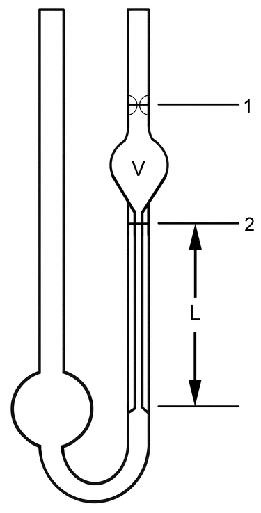
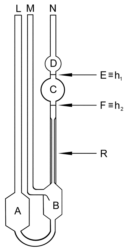
The viscosity of a Newtonian fluid is measured by the use of glass capillary viscometers, examples of which are shown in Figure 1 (simple U-tube capillary viscometer, also referred to as an Ostwald-type capillary viscometer) and Figure 2 (constant or suspended-level viscometer, also referred to as an Ubbelohde-type capillary viscometer). [Note—When the term viscosity is used herein, it refers to absolute or Newtonian viscosity. ] The constant- or suspended-level viscometer is a more robust design that is less influenced by temperature variations.
Figure 1. Simple U-tube (or Ostwald-type) capillary viscometer. [Note—Variables are defined in the text.]
Figure 2. Suspended-level (or Ubbelohde-type) capillary viscometer. [Note—Variables are defined in

 911
911
 (CN 1-May-2015)
The following example is based on Figure 1, and the same principle is applicable to Figure 2. With the apparatus in Figure 1, the flow time, t, is measured for a given volume of fluid, V, as defined between lines 1 and 2 of Figure 1, to flow through a capillary tube having a length equal to L and a radius equal to r. As long as the density of the fluid,  , is known, the viscosity can be calculated using the Poiseuille equation:
| P | = | = pressure |
The applied pressure differential, DP, is defined as:
DP = (h1  h2) × g ×


 (4)
(4)
| h1 | = | = height of the fluid in the tube at line 1 measured from the bottom position |
| h2 | = | = height of the fluid in the tube at line 2 measured from the bottom position |
| g | = | = gravitational acceleration (standard value = 9.80665 m·s |
Glass capillary viscometers generally are categorized as low shear stress instruments because DP is relatively small. The typical ranges for shear stress,  , and shear rate,
  (at the wall), are 0.1–15 Pa and 100–20,000 s
 1, respectively.
The absolute dimensions of a capillary tube usually are too difficult to measure conveniently. As a result, an empirical calibration is employed for each viscometer tube. Collecting all the constants in Equations 3 and 4 into a single viscometer constant, k, yields the approximate equation for kinematic viscosity:
To determine k, analysts measure the flow time for a liquid of known viscosity at a given temperature. This result is used to calculate the viscometer constant for that particular temperature.
In work requiring a high degree of accuracy, analysts can use the following equation:
| E | = | = kinetic energy factor, in mm2·s |
The viscometer constant, k, and kinetic factor, E, are determined from flow times measured for a set of stable, clean, Newtonian fluids of known kinematic viscosity (viscosity standard reference materials).
Once the viscometer constant(s) have been determined for a given temperature by the use of appropriate viscosity standards, the values can be used until the viscometer is subjected to thermal or mechanical stress that alters the dimensions of the capillary.
Generally, calibration, operation, and cleaning of viscometers should be performed according to instrument manufacturer's recommendations. Capillary viscometers must be scrupulously clean and should display no residual adsorbed or particulate organic or inorganic contamination. Surface contaminants may alter the dimensions of the capillary and the interfacial tension.
The procedures detailed in

 911
911
 (CN 1-May-2015)
Capillary viscometers described in  911
911 typically measure rheological properties at only one shear rate during one pass of the sample through the capillary. Because of the nonlinearity of the shear rate–shear stress relationship for non-Newtonian fluids, this measurement is inadequate unless provisions are made for flow measurements at multiple rates of shear. Even more problematic for non-Newtonian fluids are the decrease in shear rate from the capillary wall to the center of the capillary and the variation in shear stress with time as the liquid level in the capillary viscometer decreases. Thus, capillary viscometers are inherently unsuitable for use in characterizing non-Newtonian fluids.
Because of the small DP attained with glass capillary viscometers, their use in measurements of high-viscosity fluids is impractical. Capillary-extrusion viscometers that use an external pressurized gas reservoir or other source of constant pressure are the only practical capillary instrumental alternative in these instances. In addition, capillary-extrusion viscometers may allow the operator to vary the shear rate or stress, thus enabling the characterization of non-Newtonian fluids. Chapter  911
911 does not address such devices.
Measurement of Newtonian Viscosity Using a Rotational Viscometer
The principle of the method is to measure the force (torque) acting on a rotor when it rotates at a constant angular velocity (rotational speed) in a liquid. Rotational viscometers are used for measuring the viscosity of Newtonian fluids or the apparent viscosity of non-Newtonian fluids. Detailed methods and procedures for rotational instruments are provided in

 912
912
 (CN 1-May-2015)

 912
912
 (CN 1-May-2015)
Change to read:
• Non-Newtonian Rheology
Newton's law of viscous deformation or flow, described in the section on Newtonian viscosity, describes the relationship between an applied stress,  , and the resultant flow with a rate of shear, or velocity gradient, of
  . Disperse systems (i.e., suspensions or emulsions) or fluids that contain macromolecular components usually do not obey Newton's law. These exceptions to Newtonian behavior are the subject of this section. The categorization of such exceptions into different flow behaviors such as shear-thinning (pseudoplastic), shear-thickening (dilatant), Bingham, etc., is not rigid. Non-Newtonian fluids may exhibit different rheological behavior depending on shear rate, shear stress, and temperature. Time-dependent rheological behavior, such as rheopexy or thixotropy, is not considered in this chapter.
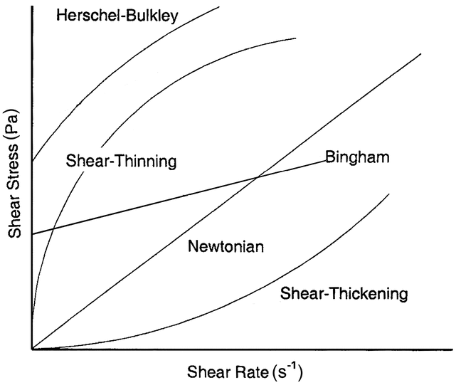
The rheological behavior of a non-Newtonian fluid is evident when shear stress is plotted as a function of shear rate. The shear stress–shear rate relationship for Newtonian compositions is linear and passes through the origin, whereas the shear stress–shear rate relationship for non-Newtonian fluids is nonlinear and may not pass through the origin, or it is linear but does not pass through the origin (Bingham body). Rheograms, or flow curves, of some typical non-Newtonian fluids are contrasted with those of Newtonian fluids in Figure 3.
All the rheograms in Figure 3 can be described by the Herschel–Bulkley equation:
| = | = shear stress, in Pa | |
| K | = | = consistency coefficient |
| = | = shear rate, in s |
|
| n | = | = the flow behavior index |
| = | = yield stress, in Pa |
For Newtonian fluids and Bingham plastics, K is designated as the viscosity ( ) and plastic viscosity (
 pl), respectively. Because the viscosity of Newtonian fluids and the plastic viscosity of Bingham plastics are independent of the shear stress or shear rate, the flow behavior index, n, is equal to 1 for Newtonian fluids and Bingham plastics. For shear-thinning fluids, 0 < n < 1, and for shear-thickening fluids, 1 < n <
  . Shear thinning can be observed in certain complex solutions such as aqueous hydrocolloid solutions. Dilatant behavior is generally exhibited by concentrated suspensions of nonaggregating monodisperse solid particles such as mixtures of corn starch and water. At very high viscosities or very low shear stresses, Bingham plastics exhibit a yield stress,
  0, a shear stress below which no apparent deformation occurs (Figure 3). Other non-Newtonian fluids do not appear to exhibit a yield stress,
  0, because flow occurs even at very low shear stresses. Thus, for non-Bingham bodies, in the absence of
  0 the Herschel–Bulkley equation reduces to the power law, i.e., the Ostwald–de Waele equation:
Many pharmaceutical macromolecular materials exhibit non-Newtonian behavior in solution. Although the viscosity of Newtonian fluids is a constant, i.e.,  =
=  /
/ so that
  is independent of shear rate or shear stress, there is no singular value of viscosity for non-Newtonian fluids because the viscosity of non-Newtonian fluids varies with shear rate or shear stress. Accordingly, applying the Newtonian concept of viscosity to non-Newtonian fluids is inappropriate. The viscosity value observed for a non-Newtonian fluid is an apparent viscosity,
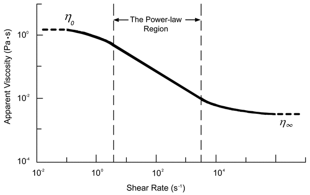
  app, and is a function of the conditions of measurement. As the shear rate or shear stress changes, the apparent viscosity is likely to change as well. Figure 4 depicts the dependence of
  app on the shear rate for an aqueous solution of a typical hydrocolloid.
Figure 4. Log–log plot of the dependence of  app on the shear rate for an aqueous solution of a typical hydrocolloid.
Figure 4 depicts apparent viscosities,  app, ranging from high values at very low rates of shear to low values at very high rates of shear. The curve's asymptotes—corresponding to the zero-shear viscosity (
 0) and the infinite-shear viscosity (
 )—together with the linear log–log region at intermediate rates of shear, are characteristic of the shear-thinning behavior of these materials.
During the course of manufacturing, in-process materials that exhibit non-Newtonian behavior may be subjected to wide ranges of shear rates and shear stresses. Fluid dynamic conditions during drug product storage and administration and release of the active constituent(s) could broaden those ranges even further. For materials that exhibit non-Newtonian behavior in a solution or dispersion, the rheological profile (rheogram or flow curve), as described in Figure 3, gives a better functional characterization than a single viscosity measurement of the apparent viscosity at a single shear rate.
Determination of the rheological profiles of non-Newtonian solutions or dispersions requires the use of a rheometer or a viscometer that is capable of measuring rheological behavior over the range of shear rates and/or shear stresses encompassing the conditions that the excipient or product is likely to encounter. The exact mathematical characterization of deformation and flow of a test substance requires the precise delineation of sample dimensions, the forces exerted, and the resulting deformation or flow. Instruments that enable a thorough, geometrically accurate analysis of deformation and flow are termed absolute rheometers. Such absolute rheometers are preferred for measurements of non-Newtonian fluids so that results can be compared from instrument to instrument for corresponding ranges of shear stresses and shear rates. When flow or deformation is not well defined or is indeterminate, the resulting measurements are likely to correspond, at best, to approximations of the true rheological behavior of the sample. Rheometers that can provide useful information about material behavior, but do not enable the true rheological character of the material to be determined, are known as relative rheometers. Such instruments are subject to geometry-dependent limitations. Results obtained with relative rheometers generally are not comparable to those obtained with absolute rheometers or other differently configured relative rheometers. Relative rheometers often are called viscometers. However, the term viscometer should be reserved for a subset of rheometers that measure only steady shear flow and the corresponding Newtonian viscosity.
Temperature control during the course of measurement is critical to the rheological evaluation of non-Newtonian fluids. An Arrhenius-type equation has often been invoked to characterize Newtonian and non-Newtonian flow properties as a function of temperature:
| = | = Newtonian or non-Newtonian viscosity at some absolute temperature T | |
| = | = Newtonian or non-Newtonian viscosity at some reference temperature Tref | |
| A | = | = constant |
| E0 | = | = energy for viscous flow |
| R | = | = universal gas constant |
Energies for viscous flow and the constant A are determined from experimental data. Energy dissipation by viscous flow is a function of measuring system geometry, temperature control, shear rate, and shear stress, but increased variability is observed in particular at high shear rates and for fluids that exhibit high apparent viscosity. Sample temperatures of non-Newtonian fluids should be controlled to ±0.1 , as is the case for Newtonian viscosity measurements.
Measurement of Viscosity Using a Rotational Rheometer
Rotational rheometers represent a more useful alternative to most capillary viscometers for measuring the rheological characteristics of non-Newtonian fluids as long as variations in shear rate, sample temperature, and edge or end effects can be minimized. The most common absolute rotational rheometer designs include concentric (coaxial) cylinder, cone-and-plate, and parallel-plate instruments. All of these are available in models that can provide absolute rheological data—that is, data that do not require substantial corrections for end or edge effects, viscous heating, or variations in shear rate or shear stress in the sample being evaluated. Rotating spindle rheometers—often described as viscometers—are relative rheometers that typically are used to assess apparent viscosity.
An additional factor with all rheometers/viscometers that must be taken into consideration, particularly with multiphase materials, is the potential formation of a thin, less-viscous layer of fluid at the wall of the instrument. When wall effects, or wall slip, occur, instrument measurements may be misleading because of the actual rheological behavior of the sample. Identification of wall effects is instrument specific. One useful method entails the comparison of results with a roughened vs. a smooth rotor. Instrument manufacturers generally provide recommendations for identification of and correction for wall slip.
Generally, calibration, operation, and cleaning of rheometers should be performed according to the instrument manufacturer's recommendations.
General chapter

 912
912
 (CN 1-May-2015)
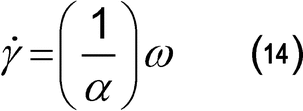
Calculation of shear rate, shear stress, and viscosity using a concentric (coaxial) cylinder rheometer:
For non-Newtonian liquids, it is essential to specify the shear stress,  , or the shear rate,
  , at which the viscosity is measured. Under narrow gap conditions (conditions satisfied in absolute rheometers), the shear rate
  in s
in s 1, and the shear stress
  , in Pa (N·m
 2 or kg·m
 1·s
1·s 2), are calculated using the following equations:
| Ro | = | = radius of the outer cylinder (m) |
| RI | = | = radius of the inner cylinder (m) |
| = | = angular velocity (radian/s) | |
| M | = | = torque acting on the cylinder surface (N·m) |
| h | = | = height of immersion of the inner cylinder in the liquid medium (m) |
Generally, the angular viscosity can be calculated using the equation:
| n | = | = rotational speed, in revolutions per min (rpm) |
For laminar flow, the viscosity  (or apparent viscosity
  App), in Pa·s, is given by the following equation:
[Note—1 Pa·s = 1000 mPa·s. ]
| k | = | = constant of the apparatus (radians/m3) |
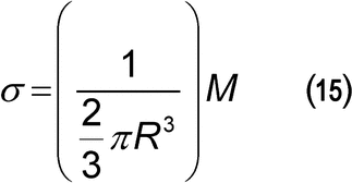
Calculation of shear rate, shear stress, and viscosity using a cone-and-plate rheometer:
The shear rate  in s
in s 1, and the shear stress
  , in Pa, are calculated by the following equations:
| = | = angle between the flat plate and the cone (radians) | |
| R | = | = radius of the cone (m) |
| = | = angular velocity (radian/s) | |
| M | = | = torque acting on the cylinder surface (N·m) |
For laminar flow, the viscosity  (or apparent viscosity
  App), in Pa·s, is given by the following equation:
| k | = | = constant of the apparatus (radians/m3) |
Measurement of Rheological Properties Using a Nonrotational Rheometer
Alternative nonrotational rheometer procedures for measuring rheological properties of non-Newtonian fluids include slit rheometers, small- and large-amplitude oscillatory shear-based rheometers, and capillary-breakup elongational rheometers. Equipment manufacturers generally provide detailed procedures, and these instruments and methods may be appropriate for use after users complete characterization and validation studies for both the equipment and the material under test. These types of rheometers are not described in

 912
912
 (CN 1-May-2015)
Auxiliary Information—
Please check for your question in the FAQs before contacting USP.
| Topic/Question | Contact | Expert Committee |
|---|---|---|
| General Chapter | Hong Wang, Ph.D.
Senior Scientific Liaison (301) 816-8351 |
(GCPA2010) General Chapters - Physical Analysis |
USP38–NF33 Page 1742
Pharmacopeial Forum: Volume No. 38(6)


